IMPORTANT:
To follow this guide, your system must be running OneView v4.3.0-114 (or newer) software. If you're managing a supported router with OneView™, please read the application note Setting Up Redundancy on Optigo Connect Spectra™ Systems with a OneView compatible Router instead.
If you're reading this article, you likely already know the benefits of having a redundant OT network, but you want a better understanding of how redundancy works in an Optigo Connect Spectra™ (PON-based) system, including how to set everything up.
Optigo has implemented an 'active/standby' redundancy system, not a 'primary/secondary' system.
In a primary/secondary redundancy system, one system is always the primary and the other system is always the secondary (or backup), which only activates when there is a primary-side failure and then hands back control to the primary system when it has recovered.
An active/standby redundancy system, on the other hand, employs more of a ‘tag team’ approach, where one side takes over if the other side fails and stays active even if the failed side recovers. Optigo's implementation does not give primary responsibility to one redundant management pair (ONS-NC600 + ONS-S8) over the other. Think of them as equal partners. Also, unless there is a total failure of one redundant pair's ONS-NC600 and/or ONS-S8, redundancy is handled laser by laser (OPT port by OPT port). So, it is possible to have some lasers on one aggregation switch in active mode (turned on and passing traffic) and some in protect mode (turned off and not passing traffic, aka standby), with the exact opposite configuration on the other aggregation switch. It is also possible to have the same laser on each system in active mode, if there is, for instance, a break in a fiber ring. In this situation, each aggregation switch would handle the portion of the fiber ring from their laser up to the break.
Before you get started setting up a redundant system, familiarize yourself with the Connect OneView™ User Guide , specifically the initial setup section. This will give you a better idea of the steps required to take a single Connect Spectra™ system (ONS-NC600 + ONS-S8) from initial connections to switch registration. Just read through it for now and be ready to reference it when you perform the steps below.
INSTRUCTIONS:
- Unbox both pairs of Network Controllers (ONS-NC600) and Aggregation Switches (ONS-S8) and mount them in the rack (or racks if you're separating them).
DO NOT POWER THEM UP OR MAKE ANY OTHER CONNECTIONS YET! - Determine which system you will initially configure as active (e.g. ONS-S8-1) and which system you will initially configure as protect (e.g. ONS-S8-2).
When physically labeling these systems or naming them in OneView, it is best to not include their initial redundancy mode (active or protect), because it is ultimately meaningless and could actually be confusing if there's an event. For example, if an active system loses power temporarily, upon restart it will switch to protect mode and stay that way until another event causes it to switch back to active mode, which may never happen. - Make sure that your core switch (e.g. router) or BMS network is configured and ready to accept connections from your management PC and the D6 ports on both ONS-S8 Aggregation Switches (refer to VLAN Modes Explained).
The ONS-NC600 network controllers must be on the same subnet for redundancy to work and your management PC must be on the same subnet as well in order to access OneView on both systems (e.g. PC = 10.12.21.100, ONS-S8-1 = 10.12.21.101, ONS-S8-2 = 10.12.21.102). - Set up the ONS-S8-1 system as per the Initial OneView Setup guide, but STOP AFTER STEP 8!
- Set up the ONS-S8-2 system as per the Initial OneView Setup guide, but STOP AFTER STEP 8!
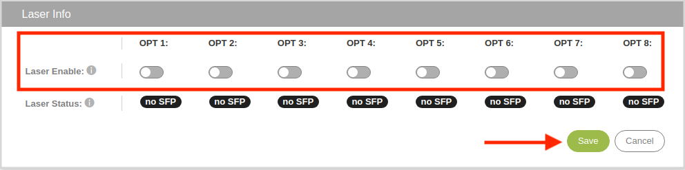
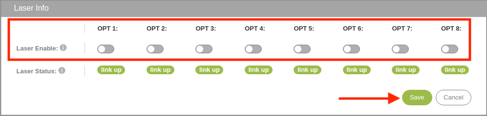
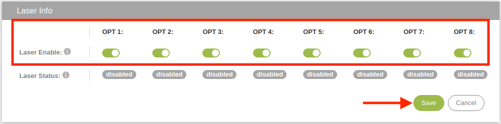
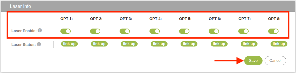
- On the ONS-S8-2 system, disable all 8 lasers (OPT 1 - OPT 8): System > Lasers
- On the ONS-S8-2 system, perform steps 9 and 10 in the Initial OneView Setup guide.
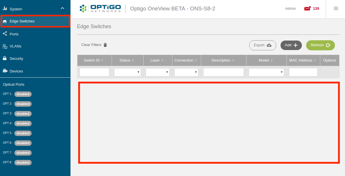
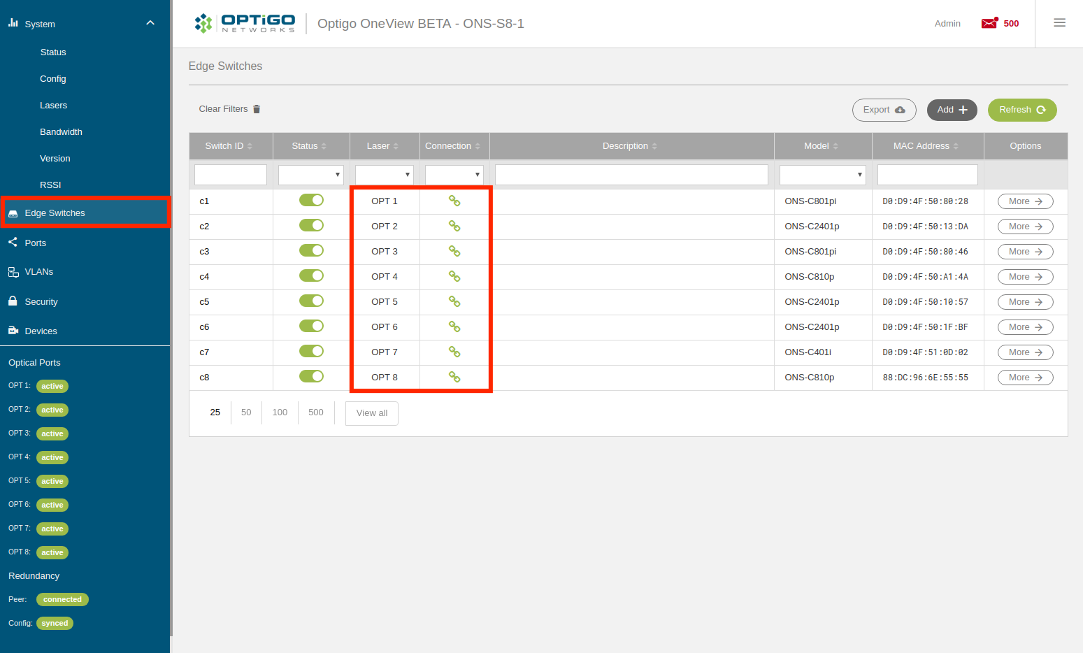
- On the ONS-S8-2 system, confirm that NO edge switches have registered.
- On the ONS-S8-1 system, perform steps 9 and 10 in the Initial OneView Setup guide.
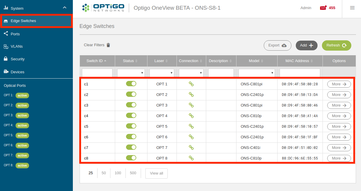
- On the ONS-S8-1 system, confirm that all of the edge switches register properly and resolve any issues (e.g. fiber, attenuation, etc).
- On the ONS-S8-1 system, enable redundancy:
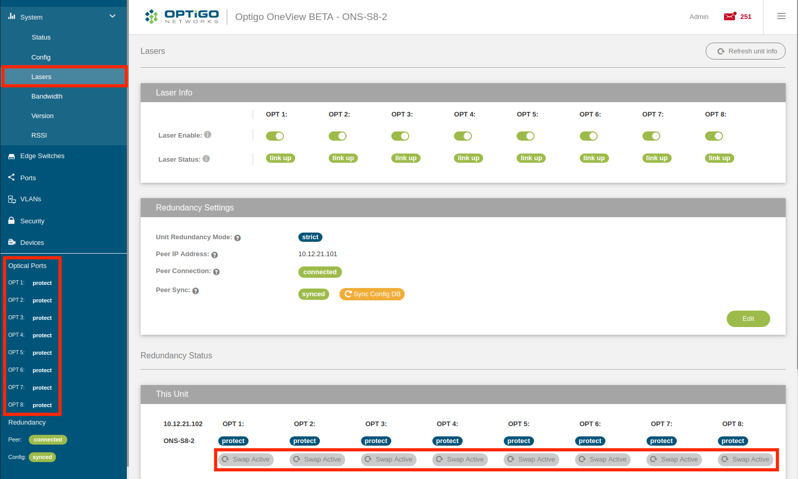
- Go to Systems > Lasers and click the 'Edit' button in Redundancy Settings.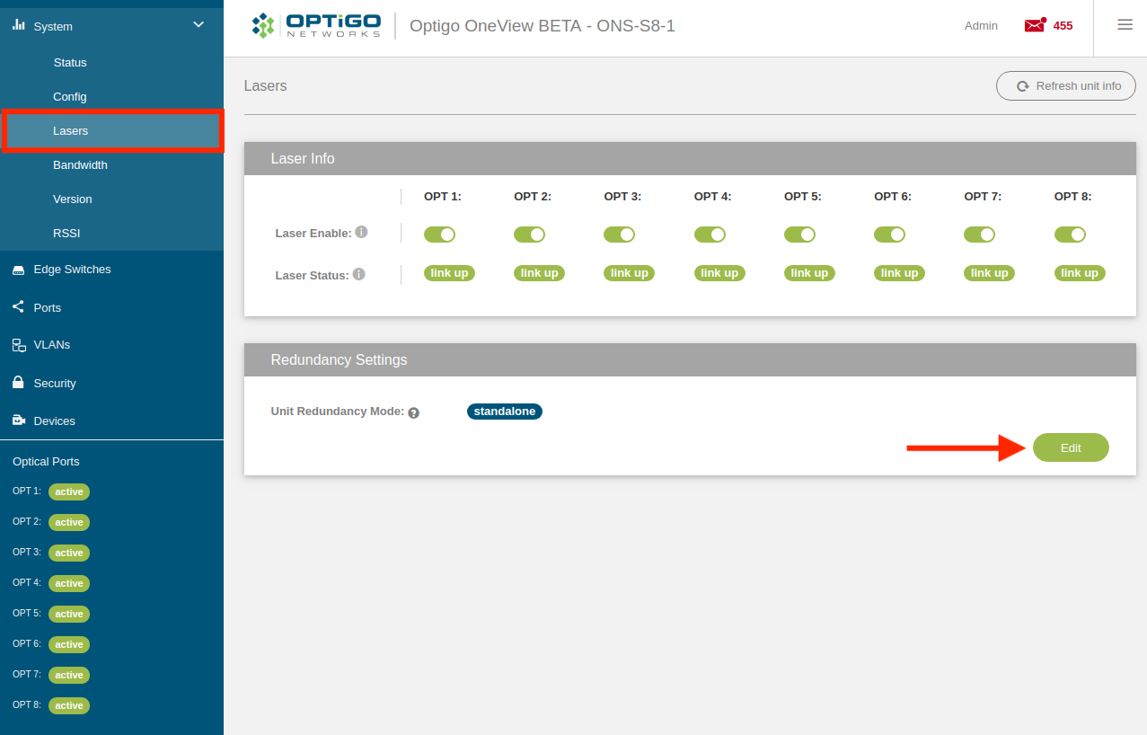
- Select Strict for the Unit Redundancy Mode.
- Enter the Peer IP Address for the ONS-S8-2 system (its management IP address).
- Click the 'Save' button.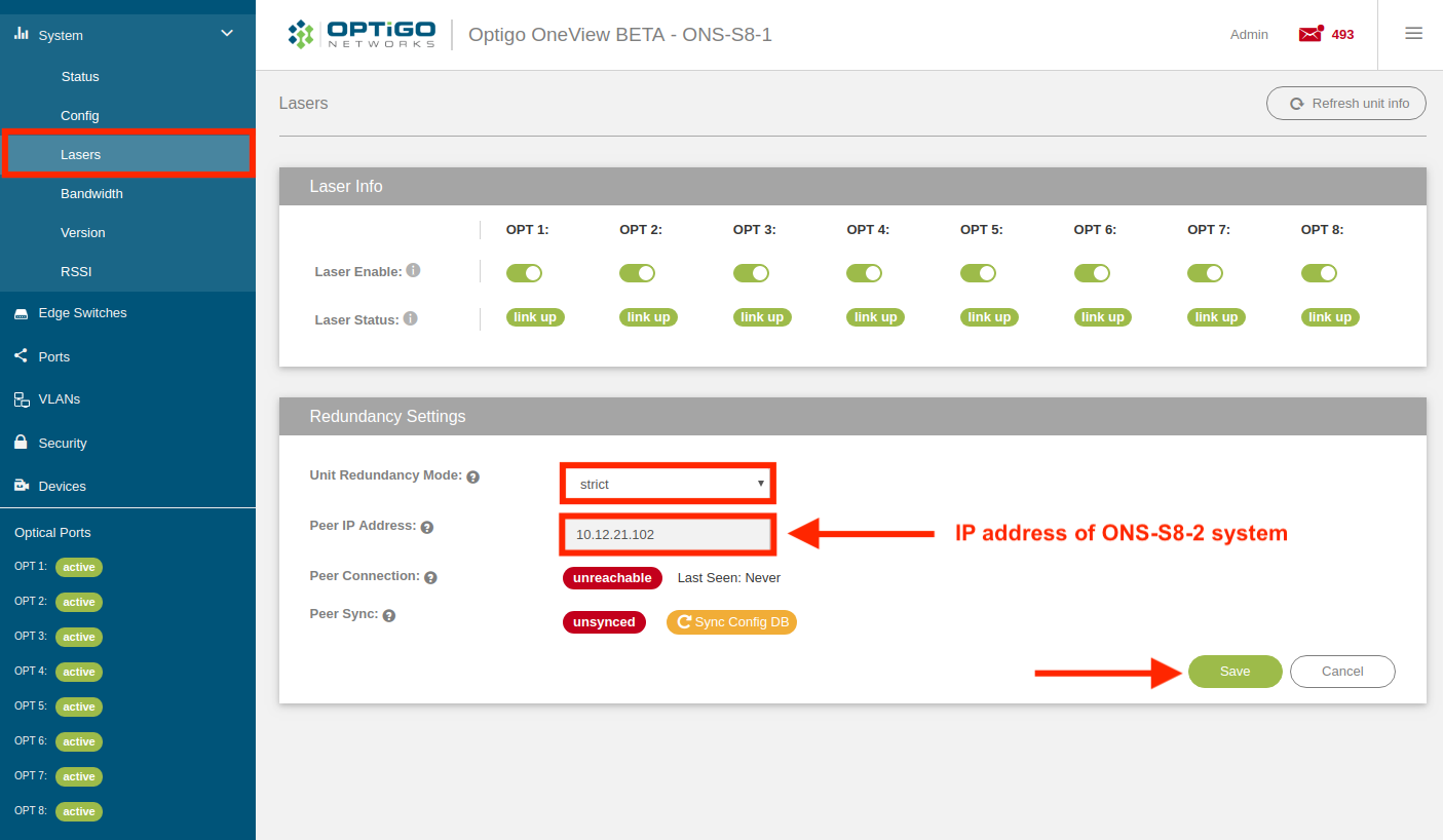
- On the ONS-S8-2 system, enable redundancy:
- Go to Systems > Lasers and click the 'Edit' button in Redundancy Settings.
- Select Strict for the Unit Redundancy Mode.
- Enter the Peer IP Address for the ONS-S8-1 system (its management IP address).
- Click the 'Save' button.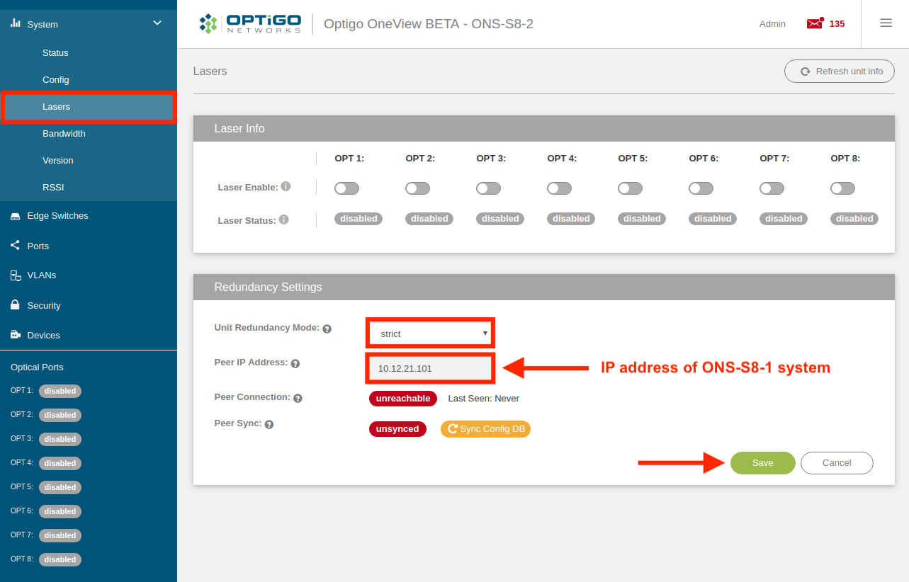
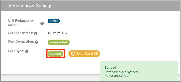
- On both the ONS-S8-1 and ONS-S8-2 systems, confirm that the Peer Connection status is connected (i.e. both ONS-S8 systems can see each other).

The ONS-S8-1 system can see the ONS-S8-2 system (10.12.21.102).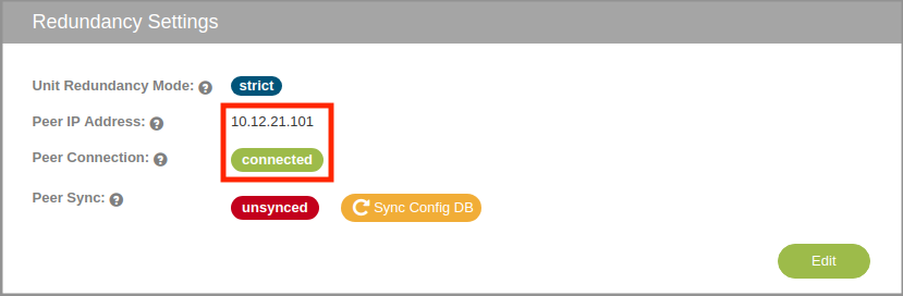
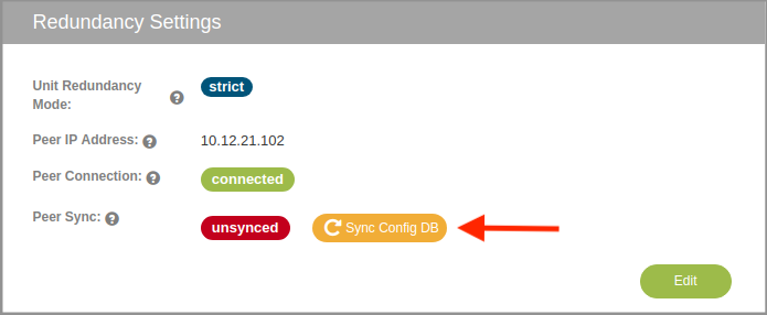
The ONS-S8-2 system can see the ONS-S8-1 system (10.12.21.101). - On the ONS-S8-1 system, click on the 'Sync Config DB' button to sync the database from the ONS-S8-1 system to the ONS-S8-2 system.
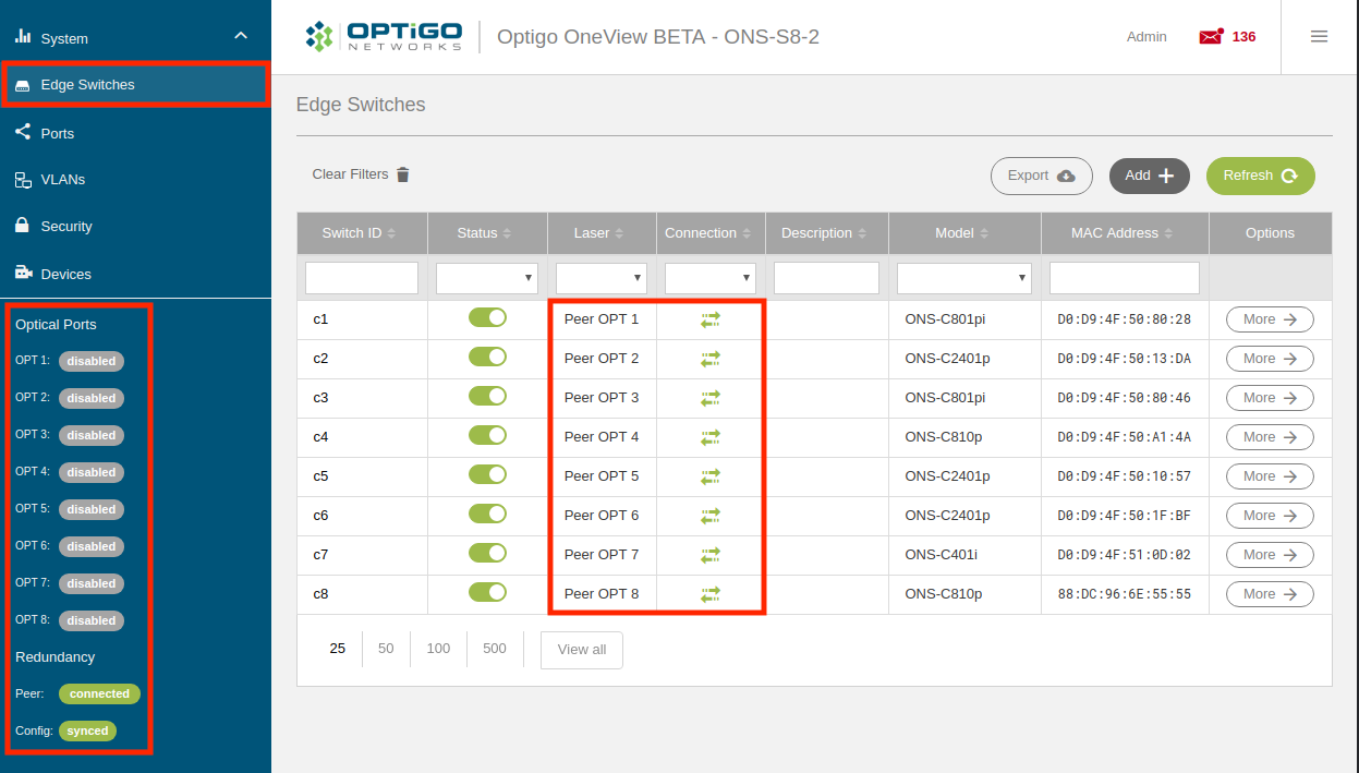
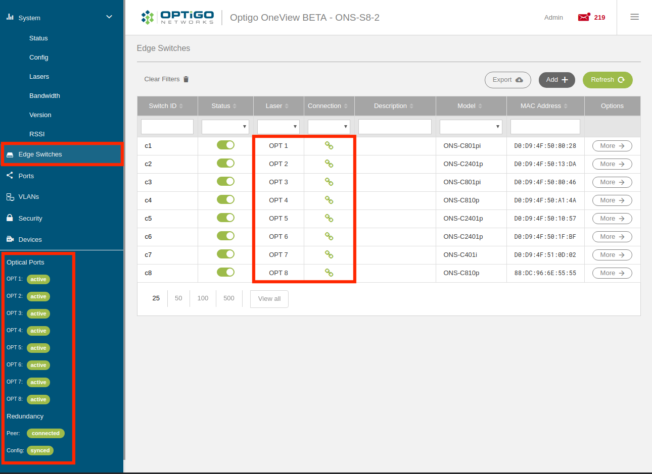
- On the ONS-S8-2 system, go to the Edge Switches page (you may have to refresh your browser) and confirm that it is populated with Edge Switches and looks almost identical to the ONS-S8-1 system's 'Edge Switches' page, except that all of the lasers on the ONS-S8-2 system should be in 'peer' mode (i.e. protect).
- On the ONS-S8-1 system, disable all 8 lasers (OPT 1 - OPT 8): System > Lasers
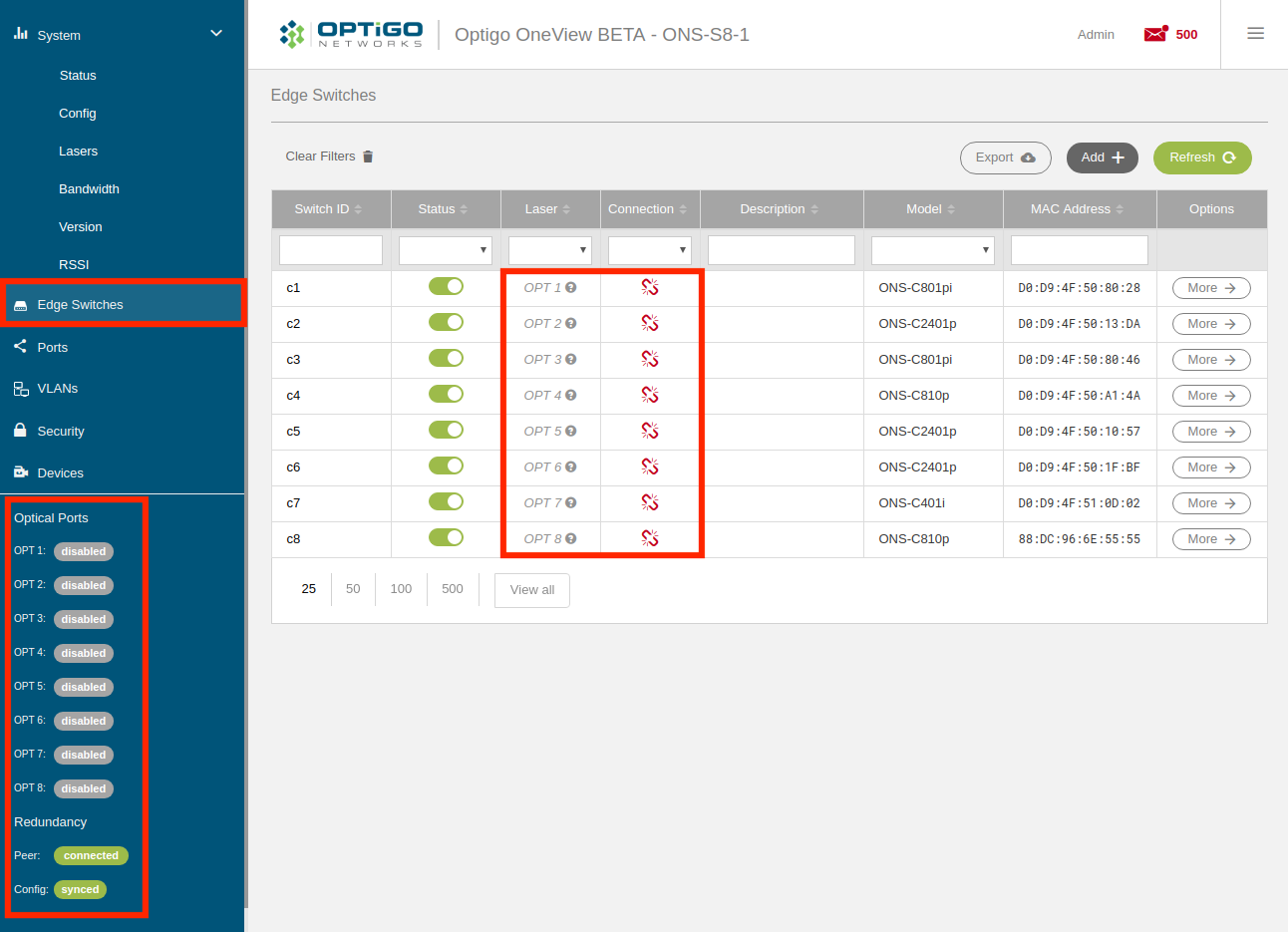
- On the ONS-S8-1 system, go to the Edge Switches page (you may have to refresh your browser) and confirm that all of the Edge Switches are now disconnected.
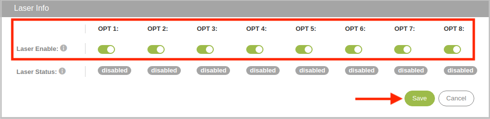
- On the ONS-S8-2 system, enable all 8 lasers (OPT 1 - OPT 8): System > Lasers
- On the ONS-S8-2 system, confirm that all of the Edge Switches register properly and resolve any issues (e.g. fiber, attenuation, etc).

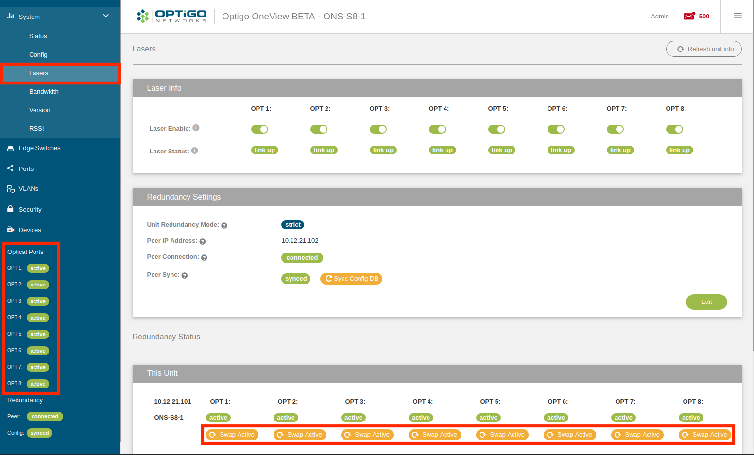
- On the ONS-S8-2 system, verify that all of the Optical Ports are set to active with a yellow 'Swap Active' button below each OPT port at the bottom.

- On the ONS-S8-1 system, enable all 8 lasers (OPT 1 - OPT 8): System > Lasers
- On the ONS-S8-1 system, verify that all of the Optical Ports are set to protect with a grayed-out 'Swap Active' button below each OPT port at the bottom.

- On the ONS-S8-2 system, verify that all Edge Switches are still registered properly and there are no issues.
- Disable all 8 lasers (OPT 1 - OPT 8) on the ONS-S8-2 system: System > Lasers

- On the ONS-S8-1 system, verify that all of the Optical Ports are set to active with a yellow 'Swap Active' button below each OPT port at the bottom.
- On the ONS-S8-1 system, verify that all edge switches are registered properly and there are no issues.
- On the ONS-S8-2 system, enable all 8 lasers (OPT 1 - OPT 8): System > Lasers
- On the ONS-S8-2 system, verify that all of the Optical Ports are set to protect with a grayed-out 'Swap Active' button below each OPT port at the bottom.
Both sides of your redundant Connect Spectra™ system should now be set up correctly and ready for OT devices to be added to the Edge Switch ports. As you do this, please ensure that the lasers on the ONS-S8-1 aggregation switch are kept in 'Active' mode at all times and periodically sync the ONS-S8-1 configuration database to the ONS-S8-2 system. If you inadvertently do something to cause the redundancy status to swap (e.g. ONS-S8-1's OPT 4 laser switches to protect mode and ONS-S8-2's OPT 4 laser switches to active mode), simply disable the laser on the ONS-S8-2 Aggregation Switch, wait for the redundancy status to swap back, and then re-enable the laser.
Once all of the OT devices on the network are operating correctly, make sure to sync the configuration database from the ONS-S8-1 system to the ONS-S8-2 system one more time.
Then, just let the everything take care of itself.
Comments
0 comments
Please sign in to leave a comment.